This unit integrates with a PC to acquire, display, and record real-time data from monitored tests conducted in the field using displacement, pressure, or load sensors.
1. Low cost
2. High precision
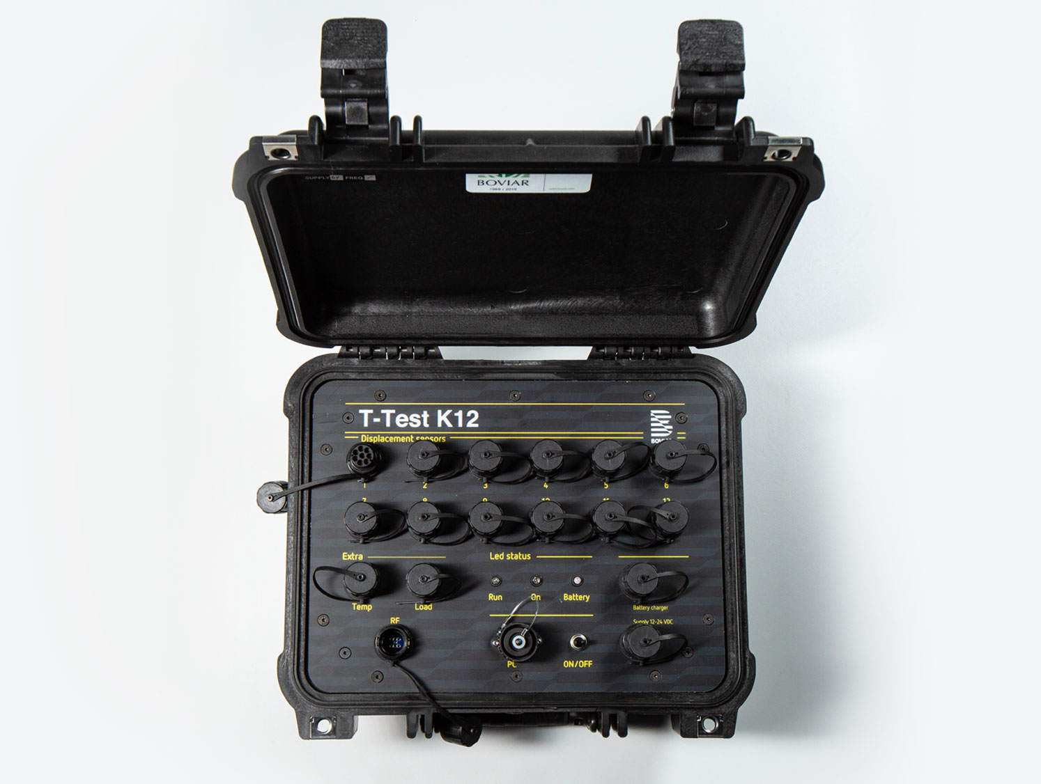
3. Practical and portable enclosure
4. Maximum acquisition frequency of 2 Hz
5. Optional wireless communication system between unit and PC
Operates on a rechargeable internal 6V battery (can also be used in buffer mode if connected to the mains). Connection to the PC is via a USB cable (included).
The unit is housed in a reinforced IP67 enclosure, easy to transport, with a minimum sampling frequency of 2 Hz and 16-bit resolution.
Can connect to:
12 displacement (or deformation, inclination, pressure, etc.) potentiometric or other
technology sensors with an analog voltage output of 0-2.5V or 0-5V or with a current
output of 4-20mA;
1 load cell
(if using a mechanical or motorized load application system) or pressure transducer or other type with a current output of 4-20mA;
1 NTC temperature sensor for ambient temperature or another type of sensor using the included 4-20mA adapter.
The included T-TEST software manages load tests (on structures like floors, piles, trusses, etc.) and other types of inspection tests.
The software acquires data from connected sensors, provides real-time visualization, and records data for later processing. If the load sensor is not connected, the software allows manual entry of the applied load value. The K12 software complements this by graphing “Force-Displacement,” “Pressure-Flow,” etc., and handles real-time zooming and exporting graphs as PNG images.
- – Analog Input Channels: 16 single-ended, including:
- – 12 with 0-2.5V or 0-5V voltage input or 4-20mA current
input (configurable in two groups of 6);
– 1 with 4-20mA current input;
– 1 with 0-2.5V or 0-5V voltage input or 4-20mA current
input (with included 4-20mA adapter);
– 2 internal channels for monitoring battery and internal
temperature.
- Resolution: 16-bit ±1 LSB
- on a 10mV to 2.5V operating r
range.
- Sensor Power Supply:
- 2.5V for displacement sensors or 12-
15V for additional sensors (load cell, pressure sensor, etc.).
- Microprocessor
- 8-bit Rabbit 3000 operating at 22.1 MHz.
- Firmware Memory
- 512 KB Flash memory.
- Real Time Clock
- Serial Interface
- RS485 Half Duplex (9600 to 115200 bps).
- Serial Interface
- RS485 Half Duplex (9600 to 115200 bps).
- Battery
- Internal 6V lead-acid, rechargeable with included charger.
- External Power Supply
- 12-24 VDC (e.g., connect to a car battery with included cables if necessary).
- Enclosure
- PELI case with IP65 protection.
- Temperature Range:
- -20 to 85°C.
- Dimensions:
- 340x300x160mm (L x H x D)
- Weight:
- approx. 4500 g.
MAIN FUNCTIONS OF T-TEST SOFTWARE :
– Calibration data entry and zeroing.
Graphical and numerical display of displacement over time.
Programmable recording intervals (1 to 60 seconds) with continuous graph updates.
Time window setting with auto-scroll.
Test graph recording and data file creation for further
analysis.
K12
The included T-TEST software manages load tests (on structures like floors, piles, trusses, etc.) and other types of inspection tests.
The software acquires data from connected sensors, provides real-time visualization, and records data for later processing. If the load sensor is not connected, the software allows manual entry of the applied load value. The K12 software complements this by graphing “Force-Displacement,” “Pressure-Flow,” etc., and handles real-time zooming and exporting graphs as PNG images.
Software: TTest and K12 for Windows Vista/7/8/10 (32 and 64 bit).
User Manual: T-Test K12.
Cables: USB connection cable
4-20mA sensor adapter
220V charger
external power source cable (12-24V).
- TR SERIES DISPLACEMENT TRANSDUCERS:
- – Available with ranges of 10, 25, 50 mm (other ranges on request).
– Potentiometric type with probe, calibrated return springs, connection cable (lengths as needed) with connector and support for an anodized aluminum telescopic rod.
– Piles Test Supports:
– Magnetic or clamp type supports for sensors during
load tests.
- – Piles Test Supports:
- – Magnetic or clamp type supports for sensors during
load tests.
- TELESCOPIC ROD
LIGHT VERSION: - – Made of aluminum, lightweight and easy to transport. – Extends to approximately 6m (closed about 2m), with adjustable tripod legs for optimal leveling.
– Sensor support in aluminum, to be purchased separately.
Total weight about 2kg.
- TELESCOPIC ROD
TOP VERSION: - – High stability version with four telescopic tubular elements (diameter 50 to 35 mm), extending to a maximum of 7.2m (closed about 2.3m).
Made of anodized aluminum, total weight about 7kg, with accessories for proper sensor positioning.
Features include a precision adjustment lever for sensor placement, a knurled and toothed base for stability on smooth surfaces, and a quick-release sensor plat
– Load tests on floors.
– Inspection tests.
– Single and double flat jack tests
– Built structure diagnostics.
– Structural monitoring.
12 months
– Sheet updated on: 2017.10;
– Specifications and standards subject to change without
notice;
– Check the website for the latest updates of the sheets,
projects, and other product photos.